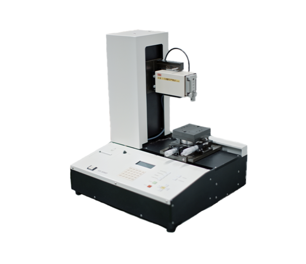
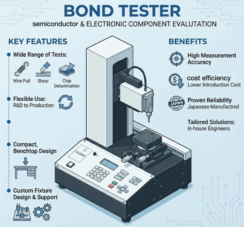
Overview
・Bond tester (strength testing machine) designed for evaluation in semiconductor and electronic component applications
・Supports a wide range of tests, including shear tests, wire pull tests, and chip delamination strength tests
・Flexible use from R&D applications to inspection and production processes
・Enables evaluations based on test concepts referenced in JIS and MIL standards
・Focuses on essential performance to achieve both high measurement accuracy and cost efficiency
・Compact, benchtop design suitable for inspection processes where over-spec systems are impractical
・Custom fixture design available for complex workpiece shapes and restrictive test conditions
・Supported by in-house mechanical design engineers for tailored testing solutions
・Japanese-manufactured system offering proven reliability
・Significantly lower introduction cost compared to equipment with equivalent functionality
Supported Tests
| (When performing shear tests) | Die shear test, ball shear test, bump shear test |
|---|---|
| (When performing pull or push tests) | Wire pull test, pull test, peel test (90°/180°), push test |
Wire pull test (destructive) (MIL standard: MIL-STD-883 Method 2011.7)
→ Gold and aluminum wires
Wire pull test (non-destructive) (MIL standard: MIL-STD-883 Method 2023.5)
→ Gold and aluminum wires
Package lead reliability test (MIL standard: MIL-STD-883 Method 2004)
→ IC packages
Lid torque test (MIL standard: MIL-STD-883 Method 2024)
→ Package sealing area
Stud pull test (MIL standard: MIL-STD-883 Method 2019)
→ Stud bonding joints
Bond shear test (JEDEC standard: JEDEC JESD22-B116A)
→ Wire bond shear
Solder ball pull test (JEDEC standard: JEDEC JESD22-B117)
→ BGA / CSP
Tensile and bend test of solder joints (IEC-compliant: JIS C 60068-2-21)
Note: The above tests are evaluations conducted with reference to the test methods and concepts described in the relevant standards. This does not indicate that the equipment itself is certified or approved under these standards.
Measurement range
Supports loads from a minimum of 2 gf up to a maximum of 50 kgf.
By selecting from four different load cells, the system covers a wide range from ultra-low forces to high loads.
Each load cell offers two measurement ranges, allowing optimal configuration based on the test method and material characteristics.
| Load Cell Types | Measurement range I | Measurement range II |
| 3kgf | 20gf 〜 3000gf | 2gf 〜 300gf |
| 15kgf | 0.1kgf 〜 15kgf | 10gf 〜 1.5kgf |
| 25kgf | 0.2kgf 〜 25kgf | 20gf 〜 2.5kgf |
| 50kgf | 0.4gf 〜 50kgf | 40gf 〜 5kgf |
Features
■ Reliable measurement accuracy with excellent repeatability
Equipped with a high-precision load cell
Measurement accuracy: ±0.1%, with load cell precision of 0.015%.
Captures even the slightest changes with high precision.
Auto-zero correction & dead zone load setting
Eliminates unwanted noise for consistent and repeatable data acquisition.
Minimizes fluctuation with ultra-low-speed control
Control range from 0.006 mm/sec to 1 mm/sec.
The micro-step motor drastically reduces drive vibration during measurement.
High precision even in deviation measurements
Even at a 150 mm offset and half of the rated capacity, the error is just 0.02%.
Accurate load values are maintained even when measurements are taken off-center.
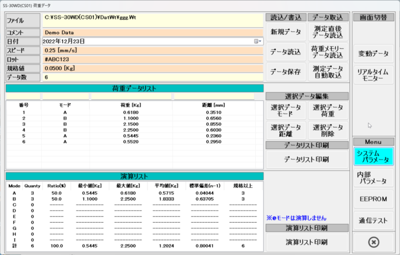
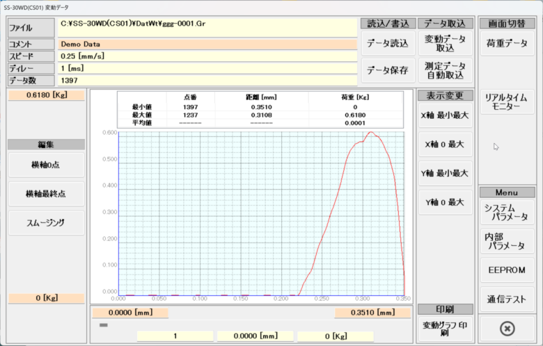
■ Data processing software that visualizes measurement results
Load data table
Displays measurement data such as maximum load, distance, and mode in a clear table format.
Saved data can be exported to Excel, making analysis and report creation smooth and efficient.
Load variation graph
Visualizes the relationship between load and displacement,
allowing you to instantly see how the load changes up to the point of sample breakage.
■ Comes standard with a JQA calibration certificate.
This product comes with a calibration certificate issued by JQA (Japan Quality Assurance Organization).
The calibration is accredited under ISO/IEC 17025, and the certificate features the JCSS and U.S. A2LA symbols, meeting both domestic and international quality control standards.
It provides reliability and peace of mind for use in research institutions and manufacturing sites where traceability is essential.
Specifications
| Measurement Range | 2gf ~ 50kgf |
|---|---|
| Load Measurement Accuracy |
±0.1% FS |
| Measurement Stroke | X-axis: 100 mm Z-axis: 100 mm |
| Stroke Setting Unit | X-axis : 1 µm Z-axis : 1 µm |
| Measurement Speed | 0.006mm/sec ~ 1mm/se |
| Axis Adjustment Range | X/Z travel: 100 mm each (0.025 µm/pulse, driven by micro-step motor) |
| Work Stage Dimensions | 100mm × 100mm |
|---|---|
| Stage X-Axis Adjustment Range | 100mm |
| Stage Y-Axis Adjustment Range | 64mm |
| Stage θ-Axis Adjustment Range | ±10° |
| Data Output | RS-232C |
|---|---|
| Data Input | Measurement date, lot number, sample number, measured value, and measurement distance data |
| Calculation Functions | Functions for calculating maximum, minimum, average, standard deviation, and fracture mode-specific analysis |
| Other Features | Auto-zero correction, safety stop function, auto step-back function, dead zone load setting, and auto return function |
|---|---|
| Options | Data processing software, heating stage, CCD camera & monitor, capture board, measurement software, and custom support for various test jigs and stages |
| Power Supply | AC 100V, 1A / Weight: 80 kg |
|---|
Application Examples by Industry
| Department | CA | R&D | Product development department |
| Final product | Semiconductors LEDs Power devices | Metal paste Resin products Home appliances | Semiconductors LEDs Power devices |
| Test content / objective | Strength testing of substrate wire frames Strength testing of bonded joints of components mounted on substrates Bond strength testing of chips mounted on wafers | Push test (destructive test) Repeated strength test | * Strength testing of substrate wire frames * Bond strength testing of components mounted on substrates * Bond strength testing of chips mounted on wafers |
Case studies
Case01: CA team
Although a bond tester was already in use for R&D purposes, it had reached its limits in both performance and operation when applied to mass production processes.
In addition, the existing equipment was aging, and rising prices for replacement systems from manufacturers had become a major concern.
As a result, the customer decided to continue using the existing system for R&D while considering an investment in a practical, cost-effective solution dedicated to production use.
• Ability to use equipment from multiple manufacturers depending on the application
• Preference for a system optimized for mass production, with a well-balanced combination of essential performance and reasonable cost
Based on these requirements, our product was selected.
Case02: R&D team
Although the customer already owned a bond tester for R&D use, it had limitations in both specifications and operational efficiency when applied to mass production processes.
In addition, the existing equipment was aging, and rising costs associated with manufacturer upgrades had become a challenge.
Therefore, the customer decided to continue using the existing system for R&D while exploring an investment in a practical, cost-effective solution dedicated to production use.
• Desire to use equipment from multiple manufacturers depending on the application
• Emphasis on a balance between essential performance and cost, suitable for mass production processes
Based on these requirements, our product was selected.
Case03: Product Development Department
In addition to the strength testing equipment already in use, the customer was looking for a new strength testing machine suitable for a different application.
• Ability to accommodate specially shaped workpieces
• Capability to support non-standard inspection methods
• Relatively low cost
Based on these criteria, our product was selected.
Comparison with other manufacturers
| manufacturer | Load measurement range | Measurement accuracy | Other specifications |
| SEISHIN【SS-30WD】 | Pull / Push: 3–50 kg Shear test: 3–50 kg | ±0.1% | Measurement speed range: 0.006 mm/s to 1 mm/s Travel range: X-axis 100 mm, Y-axis 64 mm |
| Company A | Pull / Push: 100 kg Shear test: 200 kg | ±0.1% | Measurement speed range: 0.7–50 mm/s Travel range: X, Y axes ±80 mm, Z axis 75 mm |
| Company B | Pull / Push: 100 kg Shear test: 200 kg | ±0.075% | Measurement speed range: up to 50 mm/s X-axis: 370 mm Y-axis: 168 mm Z-axis: 168 mm |
| Company C | Pull / Push: 100 kg Shear test: 200 kg | ±0.2% | Measurement speed range: 0.001–5 mm/s Travel range: X, Y axes ±50 mm, Z axis 70 mm |
inquiry
Can this workpiece shape be tested?
Is it possible to reduce costs while maintaining equivalent functionality?
Can you consult us about test methods not listed in the catalog?
To what extent can custom fixture design be supported?
What would the price be for the specifications you require?
If you have any questions or would like to discuss your requirements, please feel free to contact us via the inquiry button at the top right.